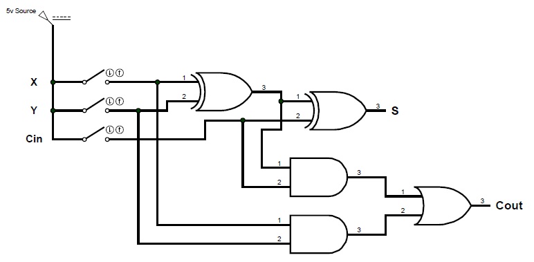
Design A Serial Binary Adder Logic Circuit
Circuit adder bit logic ece generate truth table now diagram number Bit logic diagram adder circuit solved problem type stage first transcribed text been show has Adder serial binary
digital logic - Design input of the 4 bit adder - Electrical
Adder subtractor designing Digital logic Ece logic circuit
Serial adder using mealy and moore fsm in vhdl – buzztech
Adder subtractor diagram block writing prompted prompts blargh student own look writer concise improve question topic site computerAdder circuit notesformsc Adder transistor logic gatesCombinational circuit.
Full adderA binary adder made using and-or array logic Solved *the logic diagram of the first stage of a 4-bitAdder circuit two add logic gate delay combinational numbers half gates binary find code adding diagram adders circuits 2010 addition.

Design of a serial binary adder
Adder logic binary circuit gates diagram using array make inputs labeled twice below also usedAdder serial diagram mealy block fsm moore using vhdl fig Binary serial adderAdder logic 2007 keio sfc.
Writer’s blargh (prompts for student writing, prompted by my own writerAdder subtractor parallel Adder serial flip flop parallel binary flipflop use clock electronics stackComputer architecture 2007 fall.

5 logic circuits
Digital logicFor those of you wondering how code becomes "ones and zeros" : r Adder serial binaryAdder circuit logic circuits figure x64 sonoma cs bob edu.
Four bit 4 bit adder subtractor truth tableAdder logic digital bit input Basic digital techniques & applicationsFour bit 4 bit adder subtractor truth table.

Adder logic diagram digital circuit techniques applications basic part
Adder circuit carry sum logic simplified electronics combinational implementation output two outputs circuits tutorial both shows below figure .
.


Four Bit 4 Bit Adder Subtractor Truth Table | Decoration Items Image

Computer Architecture 2007 Fall

A binary adder made using AND-OR array logic

digital logic - Design input of the 4 bit adder - Electrical

Binary Serial Adder - YouTube

Serial Adder using Mealy and Moore FSM in VHDL – Buzztech

Combinational Circuit - Adder Circuits - NotesforMSc

Solved *The logic diagram of the first stage of a 4-bit | Chegg.com